Automatic AC voltage regulator circuit under Power Supply Circuits 59563 Next.gr
Download scientific diagram | Automatic Voltage Regulator (AVR) Circuit Scheme. from publication: Automatic Voltage Regulator as a Voltage Control in 1 Phase Axial Generator.

Schematic Diagram Of Automatic Voltage Regulator Of Ac Wiring Diagram
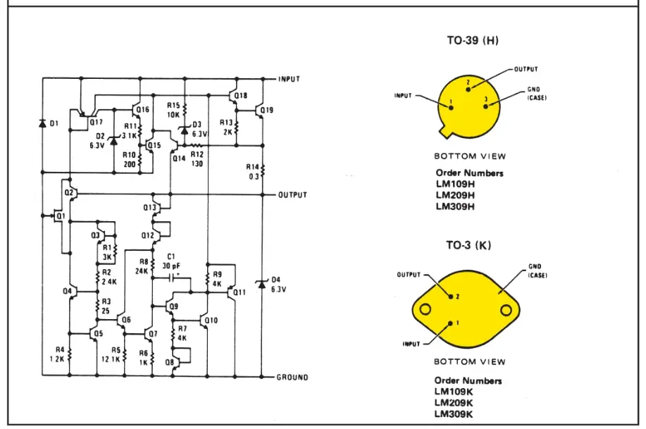
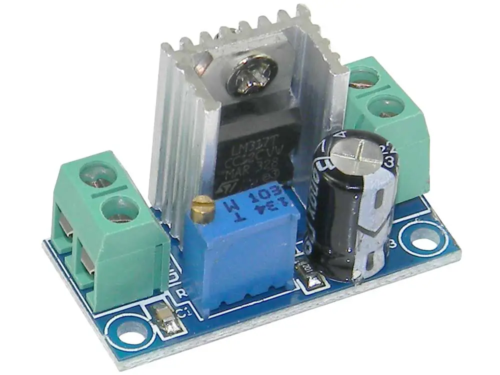
So if you want 9V, R23 could be a fixed value, i.e., 176*9 - 220 = 1k4. Note that as the internal reference is 1.25V as the lowest the regulator can go, it also needs at least 2V between input and output and has a max voltage of 32V so it can provide adjustment from 1.2V to 30V. Make R23 10k.
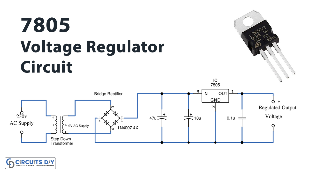
Voltage Regulator Working Principle & Circuit Diagram Voltage Regulator in Power Supply
Mecc Alte Automatic Voltage Regulators (AVR Regulator) set the precedent for AVRs in a range of industries around the world, read more here.. Management of temporary short circuits (start up of asynchronous motors) Open collector output (not insulated) signalling intervention of protective devices (insulation on optional DI1 module) with.
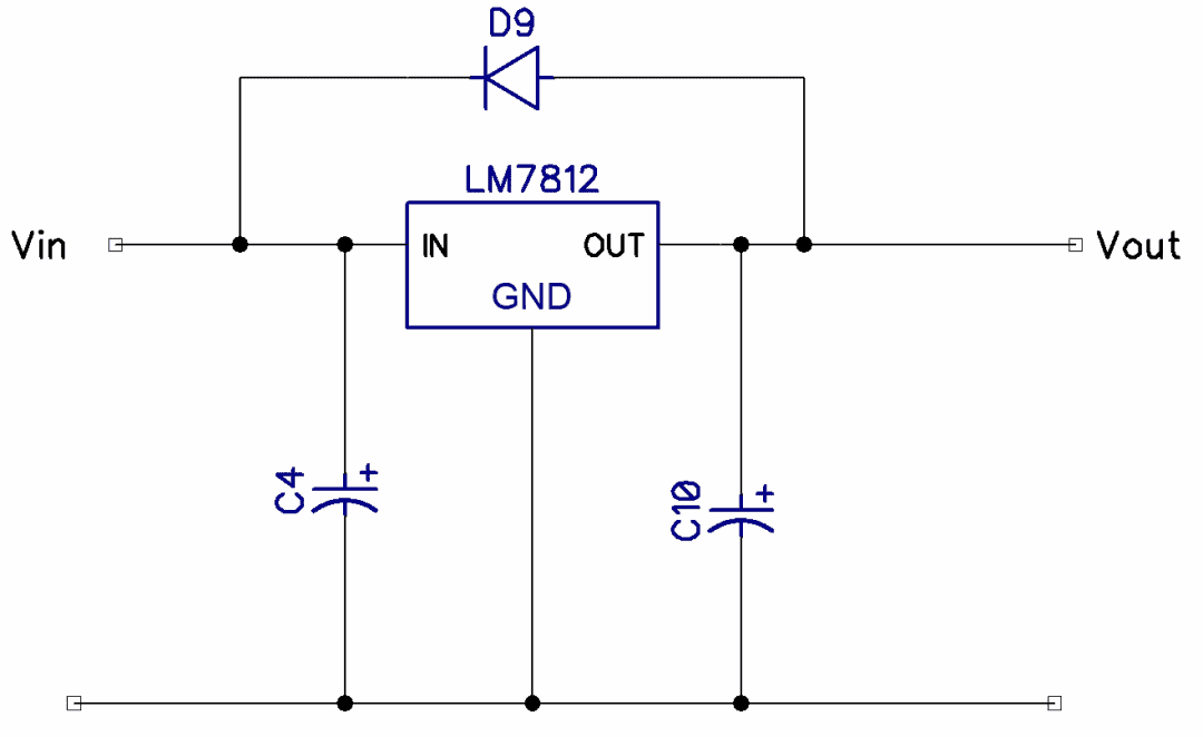
12 Volt Dc Voltage Regulator Circuit Diagram Pdf Wiring Diagram
An automatic voltage regulator circuit is a handy electronic device that ensures a steady and optimum voltage supply, protecting the devices from damage caused by under or overvoltage scenarios. In this article, we will guide you through the process of building your own automatic voltage regulator circuit, complete with a detailed diagram.

Schematic Diagram Automatic Voltage Regulator Wiring Diagram
Basically the AVR or Automatic Voltage Regulators function for generator is to ensure voltage generated from power generator running smooth to maintain the stable voltage in specified limit. It can stabilize the voltage value when suddenly change of load for power supply demand.
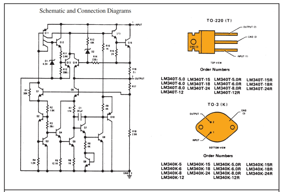
IC Voltage Regulatorswith Circuit Diagram Design & Theory
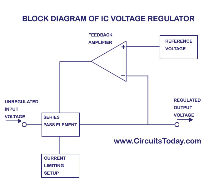
A voltage regulator is a system designed to automatically maintain a constant voltage. It may use a simple feed-forward design or may include negative feedback. It may use an electromechanical mechanism, or electronic components. Depending on the design, it may be used to regulate one or more AC or DC voltages.

LM317 Voltage Regulator Circuit Diagram
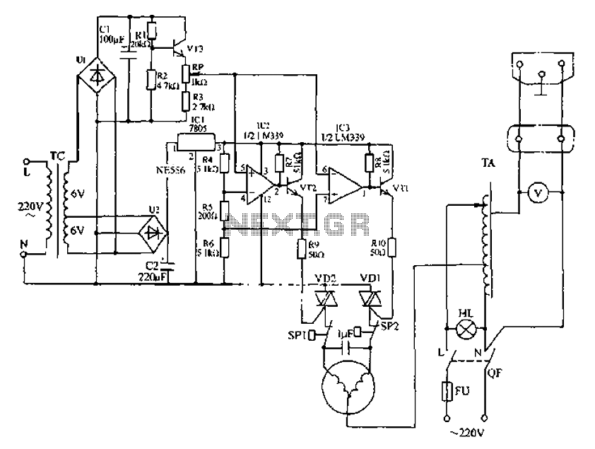
Circuit Operation: The Mains 120V AC Line and Neutral contains a switch and a fuse up to 10A. The DPDT Switch is used for Voltage up and Down. DPDT Switch has a four ends. The Neutral from mains enters directly in first end of DPDT and the Line/Phase enters the transformer primary winding which is of 220 Turns of 6 layers.
regulator circuit diagram Wiring Diagram and Schematics
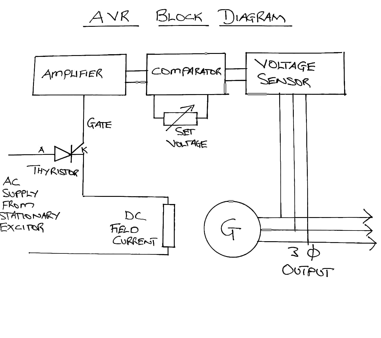
Automatic Voltage Control - Figure 8.20 gives the schematic diagram of an automatic voltage regulator of a generator. It basically consists of a main exciter which excites the alternator field to control the output voltage.
How to Make Voltage Regulator Circuits Circuit Basics
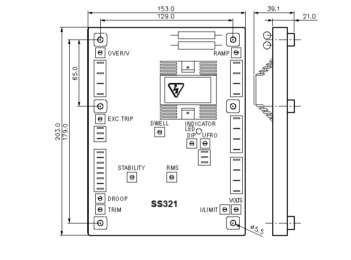
GENERAL INFORMATION 1.1 DESCRIPTION EA63-5 is an automatic voltage regulator (AVR) for AMG synchronous generator industrial application series. The AVR is typically supplied by a single-phase auxiliary winding wound into the stator slots. It also can be supplied by permanent magnet generator ˄PMG˅or phase voltage of main terminal. 1.2 SPECIFICATION
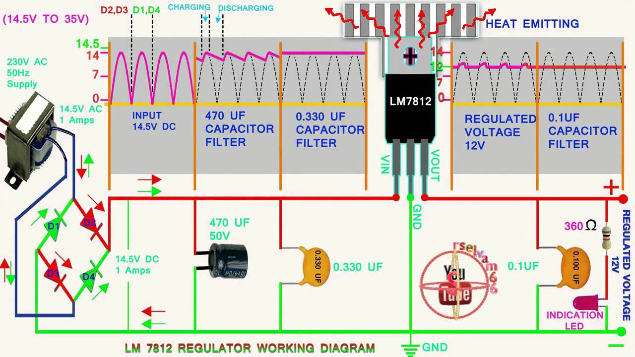
LM7812 voltage regulator working and wave form animation,how to work voltage regulator YouTube
Working, limiters & other components of AVR (Automatic voltage regulator) has been illustrated with the help of block diagrams & circuit diagrams.Easy detail.
Schematic Automatic Voltage Regulator Wiring Diagram
1. The three wires of the AVR are connected to the corresponding clips of the analyzer. 2. As soon as the analyzer is switched ON, it will apply 5 volts at INPUT and read the polarity at the output, C. 3. If the output is positive the analyzer should light up a green LED. And the voltage to be monitored across the C and B. Alternatively:
Understanding Voltage Regulation in Power Supply Voltage Regulator Circuit Diagram
What Is AVR, and Why Is It Important? An automatic voltage regulator is a device that keeps the voltage supply to electrical equipment constant. It serves as a buffer for voltage fluctuations, delivering a reliable flow of power at all times.
Integral Voltage Regulator Wiring Diagram
A voltage regulator is designed to automatically 'regulate' voltage level. It basically steps down the input voltage to the desired level and keeps that in that same level during the supply. This makes sure that even when a load is applied the voltage doesn't drop. Thus, a voltage regulator is used for two reasons:-
Voltage Regulator Working Principle & Circuit Diagram Voltage Regulator in Power Supply
The automatic voltage regulator is used to regulate the voltage. It takes the fluctuates voltage and changes them into a constant voltage. The automatic voltage regulator works on the principle of detection of errors. It controls the voltage of the system and has the operation of the limit nearer to the steady state stability.
Circuit Diagram Generator Avr
1. A general positive voltage regulator - The output voltage can be adjusted by varying the pot and resistor. There is an equation given to calculate V0ut. 2. Adjustable voltage regulator circuit - where the output voltage can be selected digitally.
AC Voltage Regulator Three PowerSupply_CircuitsFixed Power_Supply_Circuit Circuit
AUTOMATIC VOLTAGE REGULATOR - AVR DIAGRAM CONNECTIONS GUIDE Revision 00 - 07/2021. AUTOMATIC VOLTAGE REGULATOR AVR-A-OPT-06 TRIMPOT FUNCTIONS Vad: Voltage adjustments. Turning clockwise increases voltage; E1: Sensing (Input) -160-300Vca (Single phase) Stb: Stability adjustments.